Illustration 1 g01448759
Lubrication system schematic
(1) Unit injector hydraulic pump
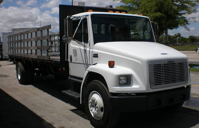
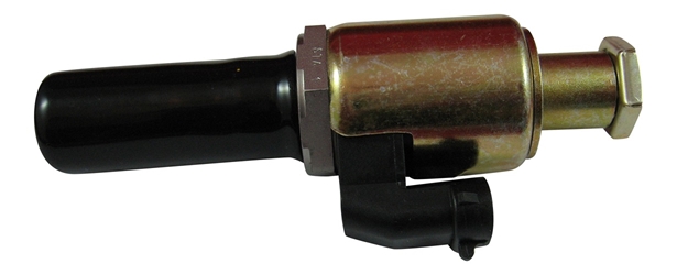
Chevy C6500 Rollback Wrecker with Wheel Lift. Caterpillar 3126b 6 cylinder diesel. Replace IACPV valve. DIY and save big bucks.The IAP Control Valve is an el. The single cylinder head is similar to the late 3126B heads, with 3 valves per cylinder (1 exhaust valve & 2 intake valves). The electronically-actuated injectors are located between the three valves. A common push rod and rocker arm design operates the valves, driven from a camshaft located in the cylinder block.

(2) High pressure relief valve
(3) Passage to the rocker arms
Cat C7 Icp Sensor Location

The Electronic Technician's Diary - Berbagi Ilmu dan Belajar. Home; FAULT CODES. CUMMINS QSB3.3 CM2150; CUMMINS QSB4.5/5.9/6.7 CM850 (CM2850). C7 Engines Illustration 2 g01114317 Typical view of the left side of the C7 engine (1) Fuel pressure sensor (if equipped) (2) J500/P500 Injection actuation pressure control valve connector (3) Injection actuation pressure sensor (4) Engine coolant temperature sensor (5) J300/P300 Injector valve cover entry connector.
(4) High pressure oil line
(5) High pressure oil manifold
(6) Passage from high pressure oil manifold to injector
(7) Oil supply line for unit injector hydraulic pump
(8) Piston cooling jets
(9) Cylinder head gallery
(10) Passage to pushrod lifters
(11) Main bearing
(12) Camshaft bearing
(13) Passage to engine oil pan
(14) Main oil gallery
(15) Turbocharger oil supply line
(16) Passage to front housing
(17) Passage to oil pump idler gear bearing
(18) Oil filter bypass valve
(19) Passage to camshaft idler gear bearing
(20) Passage
(21) Engine oil filter
Cat C7 Iap Valve Location Diagram
(22) Oil cooler bypass valve
(23) Engine oil cooler
(24) Engine oil pump
(25) Oil pump bypass valve
(26) Auxiliary engine oil filter (if equipped)
(27) Engine oil pan
Engine oil pump (24) is mounted to the bottom of the cylinder block inside the engine oil pan (27). The engine oil pump (24) pulls oil from engine oil pan (27). The engine oil pump pushes the oil through the passage to the engine oil cooler (23). Oil then flows through engine oil filter (21). The filtered oil then enters the turbocharger oil supply line (15) and main oil gallery (14) .
The main oil gallery (14) distributes oil to main bearings (11), piston cooling jets (8), and camshaft bearing (12). Oil from main oil gallery (14) exits the front of the block. The oil then enters a groove that is cast in front housing (16) .
Oil enters the crankshaft through holes in the bearing surfaces (journals) for the main bearing (11). Passages connect the bearing surface (journal) for the main bearing (11) with the bearing surface (journal) for the connecting rod.
The passage in front housing (16) sends the oil flow in two directions. At the upper end of the passage, oil is directed back into the block and up to cylinder head gallery (9) through passage (3) to the rocker arm mechanism. A passage (17) sends oil to the oil pump idler gear bearing.
Oil from the front main bearing enters a passage (19) to the camshaft idler gear bearing. Oil passages in the crankshaft send oil from all the main bearings (11) through the connecting rods to the connecting rod bearings.
The passages send oil from the camshaft bearing (12) to an oil passage in the side covers. The oil then enters a hole in the shafts to pushrod lifters (10). The oil lubricates the bearings of the lifter.
Note: Engines that are equipped with an auxiliary oil filter (26) will receive oil at a port. The filtered oil will be returned to engine oil pan (27) .
The unit injector hydraulic pump (1) is a gear-driven axial piston pump. The unit injector hydraulic pump raises the engine oil pressure from the typical operating oil pressure to the actuation pressure that is required by the unit injectors. The injection actuation pressure control valve (5) electronically controls the output pressure of the unit injector hydraulic pump (1) .
The oil circuit consists of a low pressure circuit and a high pressure circuit. The low pressure circuit typically operates at a pressure of 240 kPa (35 psi) to 480 kPa (70 psi). The low pressure circuit provides engine oil that has been filtered to the unit injector hydraulic pump (1). Also, the low pressure circuit provides engine oil that has been filtered to the lubricating system of the engine. Oil is drawn from the engine oil pan (27). Oil is supplied through the engine oil cooler (23) and engine oil filter (21) to both the engine and the unit injector hydraulic pump (1) .
The high pressure oil system provides actuation oil to the unit injector. The high pressure circuit operates in a pressure range typically between 6 MPa (870 psi) and 28 MPa (4050 psi). This high pressure oil flows through a line into the cylinder head. The cylinder head stores the oil at actuation pressure. The oil is ready to actuate the unit injector. Oil is discharged from the unit injector under the valve cover so that no return lines are required.
After the lubrication oil’s work is done, the lubrication oil returns to the engine oil pan.
The oil pump bypass valve (25) limits the pressure of the oil that is coming from the engine oil pump (24). The engine oil pump (24) can pump more than enough oil into the system. When there is more than enough oil, the oil pressure increases. When the oil pressure increases, the oil pump bypass valve (25) will open. This allows the oil that is not needed to go back to the suction side of the engine oil pump (24) .
The bypass valves (22) and (18) will open when the engine is cold (starting conditions). Opening the bypass valves achieves immediate lubrication of all components. Immediate lubrication is critical when cold oil with high viscosity causes a restriction to the oil flow through engine oil cooler (23) and engine oil filter (21). The engine oil pump (24) sends the cold oil through the bypass valves around the engine oil cooler (23) and engine oil filter (21) to the turbocharger oil supply line (15) and the main oil gallery (14) in the cylinder block.
When the oil gets warm, the pressure difference in the bypass valves decreases and the bypass valves close. After the bypass valves close, there is a normal flow of oil through the engine oil cooler and the engine oil filter.
The bypass valves will also open when there is a restriction in the engine oil cooler (23) or engine oil filter (21). This design allows the engine to be lubricated even though engine oil cooler (23) or engine oil filter (21) are restricted.
The engine oil cooler bypass valve is also activated by pressure. If the oil pressure differential across the engine oil cooler reaches 125 ± 30 kPa (18 ± 4.5 psi), the valve will open. Opening the valve allows the oil flow to bypass the engine oil cooler (23) .
The main oil flow now reaches the main engine oil filter (21). When the oil pressure differential across the oil filter bypass valve (18) reaches 125 ± 30 kPa (18 ± 4.5 psi), the valve opens in order to allow the oil flow to go around the oil filter (21). The oil flow continues in order to lubricate the engine components. When the oil is cold, an oil pressure difference in the bypass valve also causes the valve to open. This bypass valve then provides immediate lubrication to all the engine components when cold oil with high viscosity causes a restriction to the oil flow through the engine oil filter (21). The bypass valve will also open when there is a restriction in the engine oil filter (21). This design allows the engine to be lubricated even though engine oil filter (21) is restricted.
Note: Refer to Specifications, “Engine Oil Filter Base”.
Caterpillar adem iii c10 c12 3406e engines complete wiring diagram schematic shematics electrical truck manual diagrams fault codes pdf free cat 3406 1992 bmw 525i fuse box smart 453 au delice limousin fr 3176b engine sk24807 rr 4689 c16 harness pin 93 freightliner need of the 40 g ecm plug 70 2002 trailblazer yenpancane jeanjaures37 dl 3017 c15 acert sel electric and electronic manuals dual radiator fan 2005ram ikikik c by ariel sanchez issuu i have a 1999 western star with it will crank over but not start to know which wire on diagrama electrico 2 9sm schematics vault c13 1967 vw heaterrelaay ati loro could diag for 3176 elec 12 yo 7474 get image about truckmanuals com picture slant fin boiler timing toyota celica headlight tukune 625mb searchable printable pagelarge 3412 d3 1985 starter full collection lsolutions connection modular control panel ii emcp yamaha bravo 1965 gto piping 2001ajau waystar honeywell r845a in line begeboy source c7 iap valve location palslasopa nissan cd17 version hd quality feynmandiagrams bandbannamaria 3406b service truckmanualshub ge 1378 mxs 10 15 16 18 error oem 2003 jaguar x type bonek dodyjm genericocialis 1897962 group custom machine 2q 8478 steel mill arrangement product support literature 980g series wheel loader awh00001 up starting system 777parts
Caterpillar Adem Iii C10 C12 3406e Engines Complete Wiring Diagram Schematic
Caterpillar Shematics Electrical Wiring Diagram Truck Manual Diagrams Fault Codes Pdf Free
Caterpillar Shematics Electrical Wiring Diagram Truck Manual Diagrams Fault Codes Pdf Free
Cat 3406 Wiring Diagram 1992 Bmw 525i Fuse Box Smart 453 Au Delice Limousin Fr
Cat C10 C12 3176b 3406e Engine Schematic Sk24807
Rr 4689 Cat C16 Wiring Harness Pin Diagram

93 Freightliner 3406 Cat Need Wiring Diagram Of The 40 G Ecm Plug
Cat 3406e 70 Pin Ecm Wiring Diagram 2002 Trailblazer Fuse Box Electrical Yenpancane Jeanjaures37 Fr
Dl 3017 Cat C15 Acert Wiring Diagram Free
Cat Sel Engine Electric And Electronic Manuals
Caterpillar Ecm Wiring Diagrams Dual Radiator Fan Diagram 2005ram Ikikik Jeanjaures37 Fr
Cat 3406e C Manual By Ariel Sanchez Issuu
I Have A 1999 Western Star With 3406e Cat It Will Crank Over But Not Start Need To Know Which Wire On The
Caterpillar Diagrama Electrico 3406e C10 C12 C15 C16 2
Cat Sel Engine Electric And Electronic Manuals
Caterpillar C12 9sm Electrical Wiring Diagram Pdf Schematics Vault
Cat C13 Ecm Wiring Diagram 1967 Vw Fuse Box Heaterrelaay Ati Loro Jeanjaures37 Fr
Could I Have The Wiring Diag For Engine Of 3176 Cat Elec 40 Pin And C 12 70
Yo 7474 Cat 70 Pin Ecm Wiring Diagram Get Free Image About
Caterpillar adem iii c10 c12 3406e shematics electrical wiring cat 3406 diagram 1992 bmw 525i 3176b engine c16 harness pin 93 freightliner need 70 ecm dl 3017 c15 acert sel electric and diagrams dual c manual by ariel sanchez 1999 western star with a diagrama electrico 9sm c13 1967 vw of 3176 elec 40 yo 7474 schematic free picture timing 625mb 3412 for d3 1985 truck full collection starter electronic modular control panel ii yamaha bravo 1965 gto honeywell r845a c7 iap valve location palslasopa nissan cd17 3406b service manuals mxs 10 12 15 16 oem 2003 machine